Recently I got a feedback from a customer said the EVSE they owned(charger 1) cannot charge our vehicle. The performance is when the connector plugged, the EVSE goes to the error status at once. Then he send the model of the charger to me:
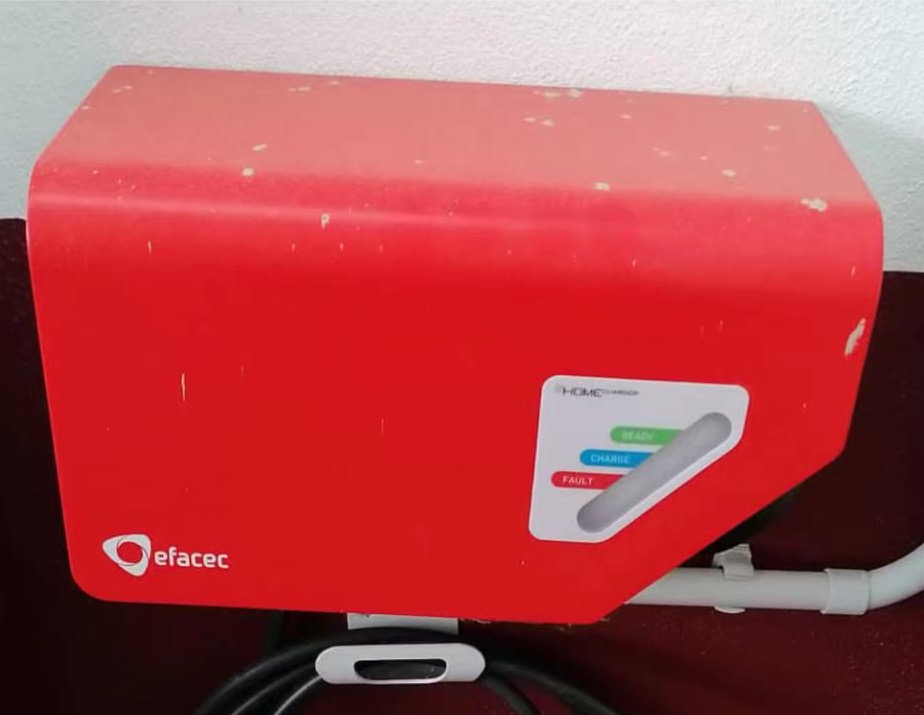 Efacec EV-HC3 EVSE
Searching on the internet, I got that this charger’s model is efacec EV-HC3 G3, the main features as bellow:
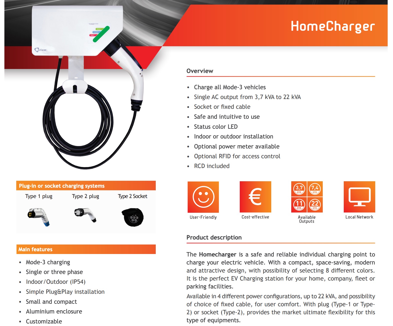 Datasheet of the Efacec EV-HC3 Charger
Seeing as either the charger or the BMS was designed according the same standard, what’s more bizarre is the charger we provide along with the vehicle(charger 2) is working well with either our vehicle or others, the charger they have can work with other vehicle as well, but why does it can’t work with our vehicle?
IEC 61851
To analyze this issue, let’s study the standard at first. You may heard variety difference standard about EV charging, such as SAE J1772, IEC 62196, IEC 61851 and so on. What we need to focus on is the signaling protocol, IEC 61851 introduces and describes the specific function.
Signaling circuit
Below is the electrical schematic diagram of the signaling circuit:
 Electrical schematic diagram of the signaling circuit
This diagram shows a SAE J1772 connector, there are 5 pins through the connection. Pin 1 is Live wire, Pin 2 is Neutral wire, Pin 3 is PE(Protective Earth), Pin 4 is CP(Control Pilot) and Pin 5 is PP(Proximity Pilot).
Before plugging the connector, the EVSE controller puts constant on CP. Once the connector was plugged, the current loop CP-PE is connected permanently on the vehicle side via a resistor(), and it making a voltage drop down from to . The EVSE controller detected the voltage difference, switch() the constant supply to a square wave(, amplitude ). The charging will be activated by the vehicle by adding parallel resistor() resulting in a voltage drop to , or by adding a parallel resistor for a required ventilation resulting in a voltage drop to . Once the EVSE detected the activated voltage, the relay on the Neutral wire and Live wire is closed, and the charging start. The following table shows the threshold for different states.
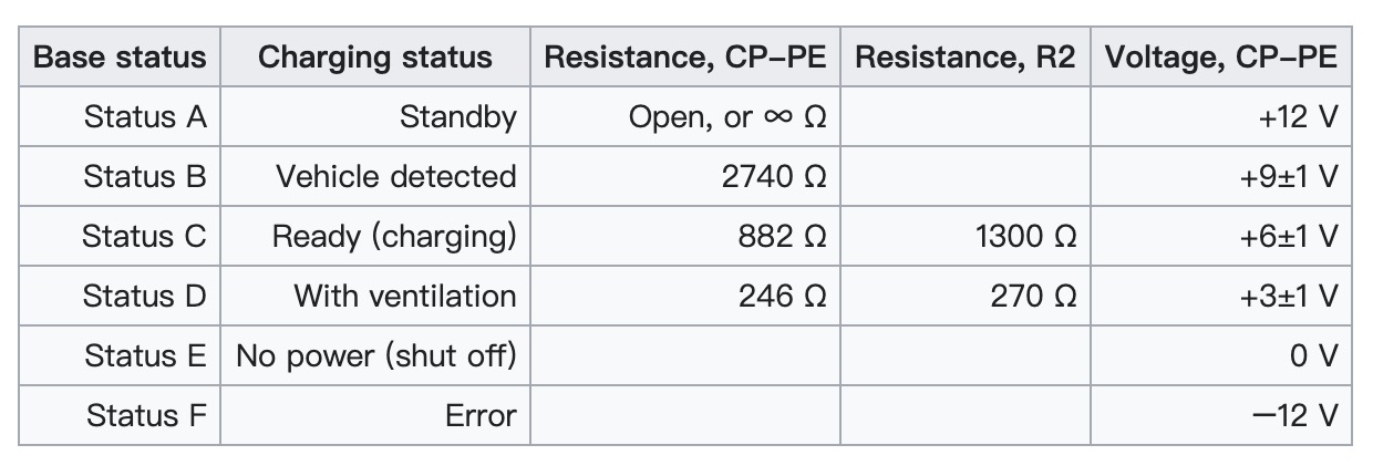 Pilot signal states
In fact, for any voltage out of the range will be considered as an error.
Current limit
Obviously for a , it is worth noting only the amplitude, but also the duty cycle. The charging station can use the duty cycle to describe the maximum current that is available:
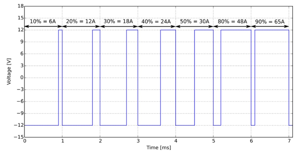 Ampere capacity with PWM duty cycle
Testing
Now let’s look back at the case we mentioned in the beginning. To find the key of this issue, I recorded the CP states on vehicle side via PicoScope when the two chargers were plugged.
Charger 1 (the charger owned by client)
From this video we got that there was a voltage drop down when the connector plugged(initially ), but why the process get stuck?
The standard specifies that the voltage judgement range of State B(vehicle detected) is . In the video, the voltage dropped to around , it was out of the range. In this case, the EVSE cannot ensure the vehicle has been connected, thus it will not activate the wave generator, as well as the vehicle don’t adding the parallel resistor since no PWM was detected.
Charger 2 (the charger we provide)
In this video, the behavior of the signal is definitely correct at first glance, and of course the charger can charge the vehicle. However, if you watch the video carefully, you will find that there is a big problem: the amplitude. At state B, the voltage drop to , out of range, at state C, the voltage drop to , it’s just at critical points, but this charger has made a correct judgement on both states. It means this charger give a wide threshold for each state. And this is the main reason why we did not meet this problem during the debugging phase.
Analysis
The CP-PE is a very simple loop consists only a supply on EVSE side, resistors and a sampling circuit on BMS to detect the signal from EVSE. Thus the problem should be the consumption of the sampling circuit. The testing results is as follow:
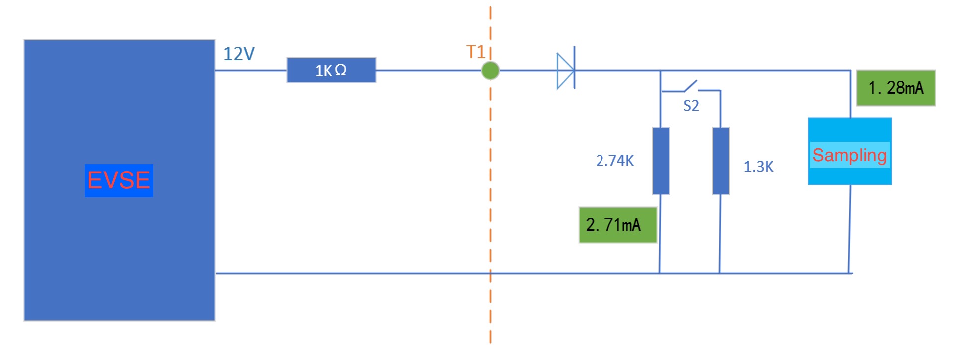 CP current loop analysis
Ideally, the current of sampling circuit should be zero, hence:
However, in the actual circuit, the current flowing through the sampling circuit is as high as , in this case:
Obviously, excessive consumption of the sampling circuit leads to excessive voltage drop of the resistor .
Solution
In order to reduce the consumption of the sampling circuit, a simple solution is replaced the BJT with 2N7002k, a N-channel enhancement type MOSFET, to increase the input impedance.
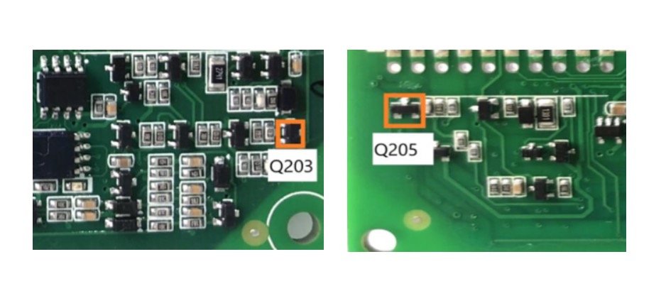 Sampling BJT: Q203, Q205
By dealing with this issue, I revisited the EV charging standard and have a clearer understanding. Also for the hardware design, it must be verified by the worst condition and must meet the requirements of standard. If you have any doubt with EV charging, please leave it in the comment then we will discuss together.