Last week I met a new issue with our vehicle: pre-charge failure. The behavior was that the negative contactor and the pre-charge relay closed then open after turn on the key. After checking the whole pre-charge circuit I found that the pre-charge resistor was damaged.
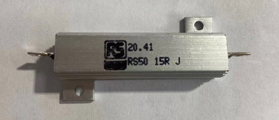 Pre-charge resistor
This is the first time that a pre-charge failure has occurred, of course it caught my attention.
Principle and function
In the power system of an EV, the power battery is connected to a lot of high voltage components via PDU(Power Distribution Unit), such as the motor controller, OBC, DC-DC, A/C(Air Condition), PTC and so on. Usually in these components there are capacitor, especially in the motor controller, the capacity of capacitor could over . If the initial capacity is zero, once power on, it is equivalent to a short circuit, and the current is so large that the battery, contactor and others components will be damaged. Therefore, a pre-charge circuit is necessary for the power system to protect the main contactor, motor controller and so on.
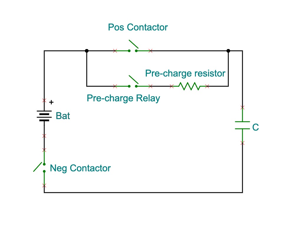 Pre-charge circuit
This is a typical first-order series circuit. Assuming that the capacity was zero at the beginning, due to the KVL function we got:
Then:
Where:
Thus:
At this point, it is concluded that after period, the charging process is over.
Theoretical basis
For the selection of pre-charge resistor, specifically, it includes three parameters: resistance , average power , and peak power . Others input parameters such as pre-charge time, capacitance value, and battery voltage are known.
Assuming that the voltage of power battery in full charge is , the capacitance of the capacity in motor controller is , the pre-charge time is , which is:
Resistance computing
According to the above equation, we stipulate that the capacity has been charged after time, which is:
thus:
Average power computing
The average power of the pre-charge resistor is:
where , .
thus:
Peak power computing
The peak power occurs when the capacitor is zero:
Simulation
Now let us verify the theory calculation above via a simulation model.
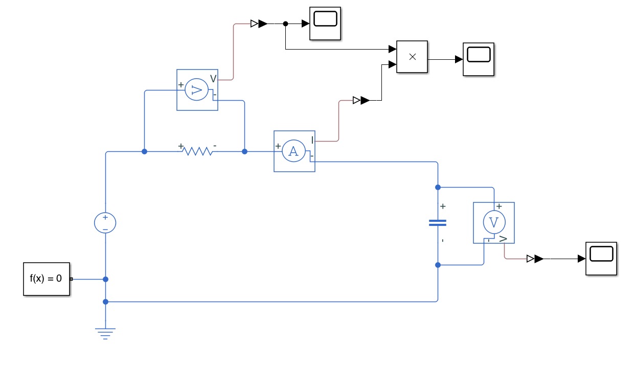 Pre-charge simulation
From the simulation we got at :
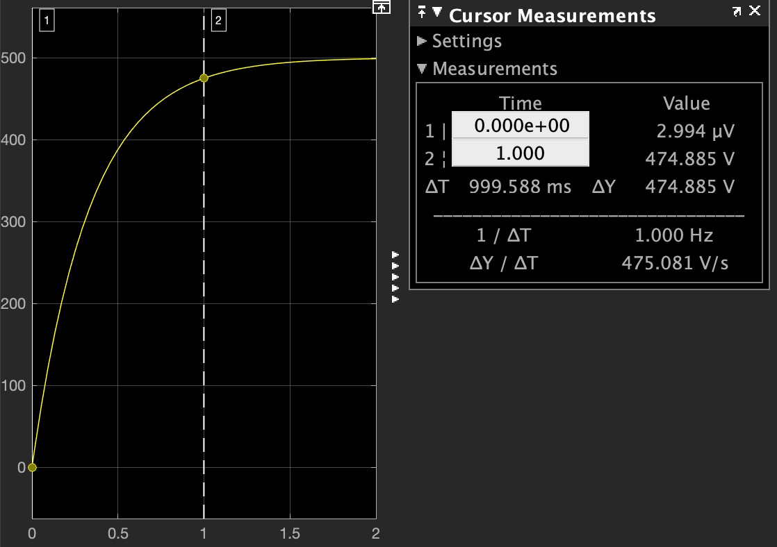 Capacitor voltage
What we have to caution is the behavior of the pre-charge resistor’s power:
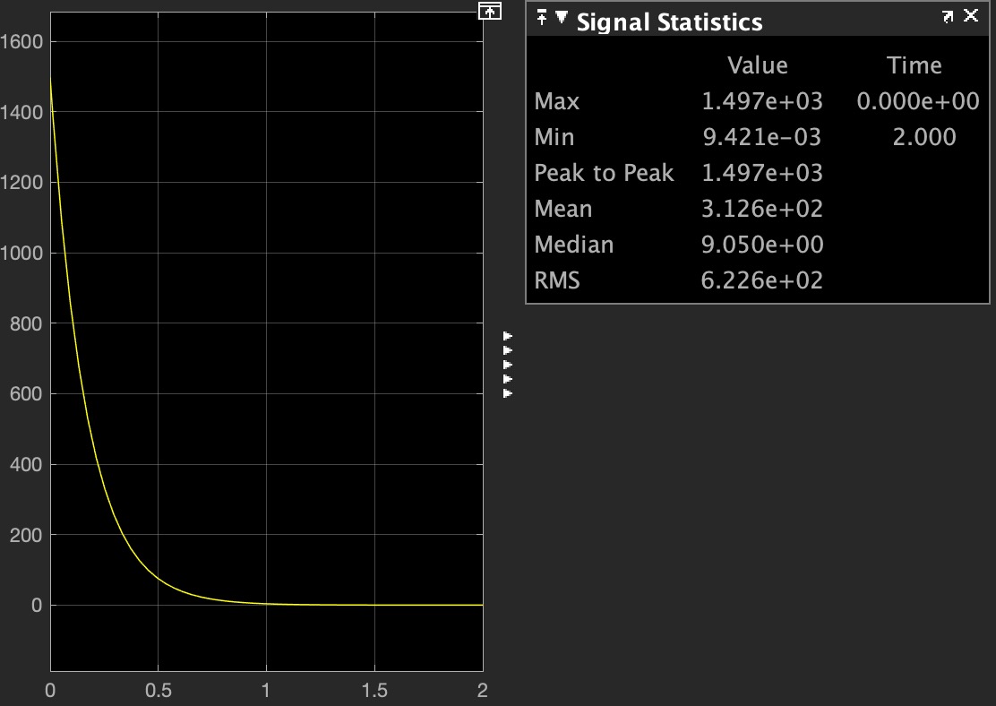 Power behavior
As you can see, the peak power of the pre-charge resistor is while the moment the contactor closes, which verified the correction of our calculation.
Realistic basis
From the calculation we got the main parameters of the pre-charge resistor is:
Below is a temperature rise curve from the datasheet of YAGEO pre-charge resistor:
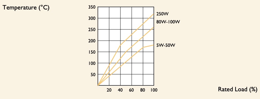 YAGEO temperature rise curve
According to this curve, the temperature will rise up over if a pre-charge resistor with rated power of is at full load. Generally the pre-charge resistor is a wire-wound resistor with a ceramic shell or aluminum shell, like this:
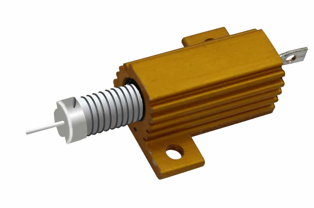 Internal structures of a pre-charge resistor
In fact, in a very short time, the heat cannot spread via the aluminum shell or ceramic shell, it’s likes a transient pulse charging process. So the power selection for a pre-charge resistor is based on the maximum power, not the steady-state power. Usually on the datasheet, it must have the description of the peak power, for example:
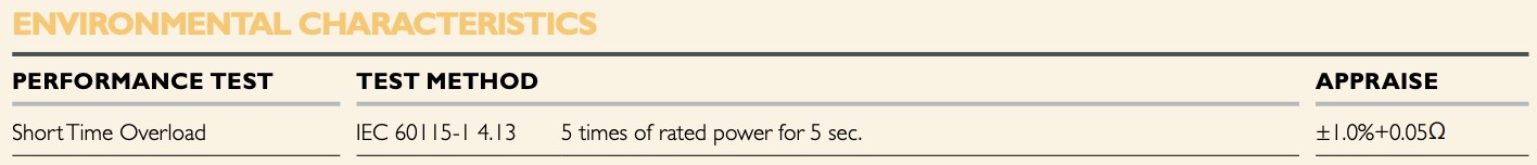 YAGEO short time over load
“5 times of rated power for 5 sec”, It means we can consider the peak power with 0.2 times derating. For our example the will be derated to . At this point we can initially determine the model of the pre-charge resistor:
On the other hand, there is a case need to be paid much more attention which is “high frequency operation”. Imaging that someone turn the vehicle on and off repeatedly in a short time. In this case, the pre-charge resistor was at a fully loaded state for a long time, and the temperature will increased so high that the resistor could be damaged. Therefore the power of the resistor must be reserved a proper margin.
Conclusion
This article discussed the pre-charge resistor selection from the perspective of theoretical calculation. In fact, the theoretical calculation can be not only as a basis of model selection, but also used for the failure analysis. In the practical implementation, there are a lot of factors will affect the selection, and all of the experience gained in practice is very valuable.